
Railway Equipment Explained: Rolling Stock, Track, and Signalling Basics

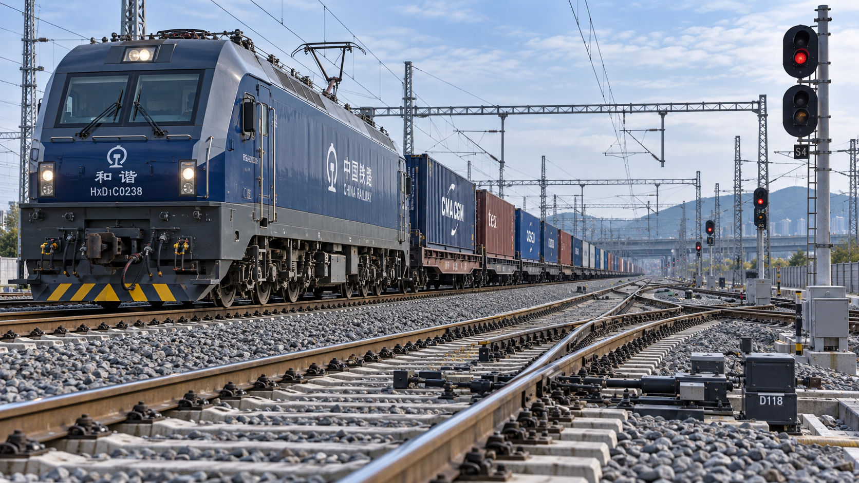
Railway equipment forms an interconnected system: rolling stock carries the load, track supports and guides it, and signalling controls when and where trains can move. A locomotive’s power, a wagon’s capacity, or a signalling system’s sophistication has meaning only in relation to the railway where it operates. Route geometry, axle loads, braking performance, and movement authorities determine how these assets work together.
Reliable railway equipment information therefore connects component specifications to operating conditions. A freight wagon might fit the track gauge yet exceed a bridge’s permitted loading. A powerful locomotive might struggle to start a heavy train on wet rails. These relationships explain why railway engineering treats vehicles, infrastructure, and train control as parts of one operating system.
Rolling stock: the vehicles and what they carry
Rolling stock includes locomotives, passenger vehicles, freight wagons, and many vehicles used for inspection or maintenance. Locomotives provide traction to haul other vehicles. Multiple-unit trains distribute traction equipment within a connected formation, so a separate locomotive is unnecessary. Freight wagons generally rely on locomotives for movement, with their design shaped by the cargo and loading method.
Open-top wagons suit bulk commodities loaded from above, while covered wagons protect goods from weather. Tank wagons contain liquids or gases within cargo-specific containment systems. Intermodal wagons secure containers or other compatible loading units. Payload alone does not establish suitability: cargo density, restraint arrangements, discharge equipment, and the vehicle’s permitted dimensions also matter.
Power, tractive effort, and adhesion
Diesel-electric locomotives use a diesel engine to drive a generator or alternator, supplying electricity to traction motors. Electric locomotives draw power from an external supply, commonly through overhead equipment or a conductor rail. Neither arrangement means that every vehicle can operate on every electrified route; supply voltage, current type, collection equipment, and control compatibility must match.
Power describes the rate at which work can be done, while tractive effort describes the pulling force available at the wheels. Starting a heavy train requires sufficient force without wheel slip. At higher speeds, available power increasingly limits the pulling force that can be sustained.
Adhesion is the grip between wheel and rail. Water, leaf contamination, oil, and other surface conditions affect it. Adding power does not automatically increase usable pulling force once adhesion becomes the limit. On sustained gradients, train mass, gradient resistance, traction capability, and equipment thermal limits all influence the speed that can be maintained.
Wheelsets, bogies, and vehicle loading
A conventional wheelset consists of two wheels fixed to an axle. Bogies support the vehicle body through suspension and allow wheelsets to negotiate curves. Their design influences stability, ride quality, wheel wear, and the forces transmitted into the track. Wheel profiles and rail profiles work together to guide the vehicle; the flange provides guidance particularly through curves and track features.
Axle load is the load carried through one axle. For example, an evenly loaded four-axle wagon with a gross mass of 100 tonnes has an average axle load of 25 tonnes. That arithmetic does not establish route acceptance: uneven loading, dynamic forces, bridge restrictions, and the infrastructure’s permitted loading must also be considered.
Brakes and couplers shape train behaviour
Train brakes must control speed on descents and stop the formation within the distances assumed by its operating and signalling arrangements. Friction brakes apply blocks to wheel treads or pads to discs. Dynamic braking uses traction motors to produce retarding force; depending on the equipment and electrical network, energy is dissipated as heat or returned to the supply.
Dynamic braking reduces demand on friction brakes, but its availability and effectiveness vary with speed and system conditions. Stopping and holding requirements still need an appropriate friction-braking arrangement. Repeated braking on a long descent also creates a thermal problem: equipment must absorb or dispose of energy without exceeding its limits.
In a conventional automatic air-brake system, reducing brake-pipe pressure commands a brake application. A separation that vents the pipe is designed to initiate braking. On a long train, pneumatic commands take time to propagate, so brake applications do not develop identically at every vehicle. Electronically controlled pneumatic arrangements improve command coordination where compatible equipment is fitted.
Couplers transmit pulling and compressive forces between vehicles. During acceleration, braking, or changes in gradient, these forces vary along the train. Slack movement, uneven braking, and tight curves can combine to create substantial longitudinal and lateral loads. Train length therefore affects handling as well as capacity, and coupler compatibility includes strength, geometry, and associated brake connections.
Track infrastructure carries and distributes the load
Rails provide a running surface and guide the wheels. Fastenings hold them to sleepers, also called ties, which maintain their position and distribute loads into the supporting structure. On ballasted track, crushed stone supports the sleepers, assists drainage, and provides resistance to movement. Beneath it, the formation and subgrade must carry repeated loading without excessive settlement.
Slab track supports the rails through a concrete-based structure instead of a conventional ballast bed. It changes construction, adjustment, and maintenance requirements. The choice between track forms depends on ground conditions, access, traffic demands, and the ability to accommodate future movement. A stable rail support is difficult to maintain over a weak or poorly drained foundation.
Gauge alone is insufficient to establish vehicle compatibility. The loading gauge defines the permitted vehicle and load envelope, while infrastructure clearances account for structures and the space required around moving vehicles. Suspension movement, curve overhang, and track geometry affect the space a vehicle occupies. A container-and-wagon combination must fit the route’s clearance limits as a complete loaded vehicle.
Points, crossings, and maintenance
Turnouts direct trains between tracks. Movable switch rails establish the selected route, while crossings allow wheel paths to intersect. These locations introduce changes in support and guidance, making condition, geometry, and operating speed especially significant. Point detection confirms the required switch position within the signalling arrangement; physical alignment and secure locking remain necessary.
Maintenance addresses different failure mechanisms. Tamping corrects geometry by adjusting track position and compacting ballast beneath sleepers. Rail grinding restores the running profile and removes some surface damage. Ultrasonic inspection looks for internal rail defects, while drainage work tackles water-related loss of support. Repeated geometry deterioration at one location can indicate a foundation or drainage problem that tamping alone will not resolve.
Signalling controls movement through the network
Signalling establishes the conditions under which a train is authorised to proceed. Its basic functions include detecting train occupancy, setting and protecting routes, communicating movement authorities, and enforcing restrictions where train-protection equipment is provided. A movement authority gives permission to proceed to a defined limit under specified conditions.
Interlocking prevents incompatible routes from being authorised together and verifies relevant conditions, such as point position. It connects the requested train movement to the state of the infrastructure. A signal showing permission to proceed therefore depends on more than whether the next stretch of track appears empty.
Track circuits detect occupancy through the electrical behaviour of a rail section. Axle counters compare axles entering and leaving a section to determine whether it is clear. Their installation and operating requirements differ. Neither technology, by itself, provides every piece of information about a train’s identity, speed, integrity, or ability to stop.
Blocks, cab signalling, and automatic protection
Fixed-block signalling divides a route into defined sections and separates trains using occupancy and movement-authority rules. More advanced arrangements use additional information about train position and braking capability to manage separation. Describing a system as digital does not reveal whether it uses fixed blocks, moving blocks, or another operating arrangement.
Cab signalling presents movement information inside the driving cab. Automatic train protection supervises compliance with permitted speeds and authority limits, intervening when required. Systems such as the European Train Control System, or ETCS, support train-control functions within defined technical and operating configurations. Communication-based train control, or CBTC, is widely associated with urban rail; its label alone does not establish suitability for a freight corridor.
Radio provides a communication channel for systems that require data exchange, but radio coverage is only one part of the safety architecture. Position determination, message integrity, braking models, onboard equipment, and behaviour after a communication failure must work together. A lost connection must lead to the response defined for that system and operating situation.
Capacity emerges from the interfaces
A heavier train illustrates the connection between all three equipment groups. Higher gross mass changes traction and braking requirements. If that mass is carried through higher axle loads, track and structures must support the resulting forces. If capacity is increased by adding wagons, train length affects siding accommodation, handling, and the time required to clear junctions.
Stopping distance is another shared constraint. It depends on speed, gradient, available adhesion, brake performance, and response time. Signalling must allow for the relevant braking assumptions. Installing newer signalling equipment does not remove the physical distance required to stop a loaded train.
Similarly, closer train separation does not guarantee a matching increase in corridor throughput. Junction conflicts, station dwell times, terminal handling, and differences between fast and slow trains can constrain capacity. A mixed passenger-and-freight route presents different scheduling and equipment interactions from a railway carrying similar trains at similar speeds.
Reading specifications in their operating context
Useful equipment documentation states both the rating and its conditions. Continuous traction capability differs from a short-duration maximum. Wagon payload must be read alongside tare mass and permitted gross mass. A maximum vehicle speed does not establish the permitted speed on every curve, turnout, or route.
Standards references also need context. Railway specifications draw on different national and international frameworks, with requirements varying by subsystem and network. A statement that equipment follows a named standard is meaningful only when its scope, applicable edition, configuration, and evidence of conformity are identified. Mechanical compatibility does not automatically establish electrical, braking, or signalling compatibility.
For an unfamiliar vehicle or system, the most revealing question is often where its stated performance stops applying: on a steeper gradient, under reduced adhesion, with a different train formation, or at a network boundary. Those limits turn an isolated specification into usable railway equipment information.
- Sizing a Narrow-Gauge Locomotive for Tunnel Muck Haulage CyclesTime : Oct 31, 2026
- Battery vs Diesel Tunnel Locomotives: Ventilation and Operating Trade-OffsTime : Oct 31, 2026
- Choosing a Narrow-Gauge Tunnel Locomotive: Clearance, Grade and PayloadTime : Oct 31, 2026
Industry Briefing
Get the top 5 industry headlines delivered to your inbox every morning.