
How Do Railway Buffers Affect Coupling Safety?

How Do Railway Buffers Affect Coupling Safety?
How do railway buffers affect coupling safety? For railway operators, rolling stock engineers, and freight fleet managers, the answer starts with how compressive forces are controlled between vehicles. In buffer-and-screw coupling systems, correctly specified and maintained buffers absorb impact energy, limit damaging shocks, and help manage vehicle interaction during shunting and braking. Worn components, incompatible buffer characteristics, or incorrect coupling adjustment can increase equipment damage and operational risk. This article examines buffer performance, inspection priorities, and coupling compatibility to help decision-makers strengthen safety across demanding freight operations.
The coupling connects the vehicles; the buffers control compression
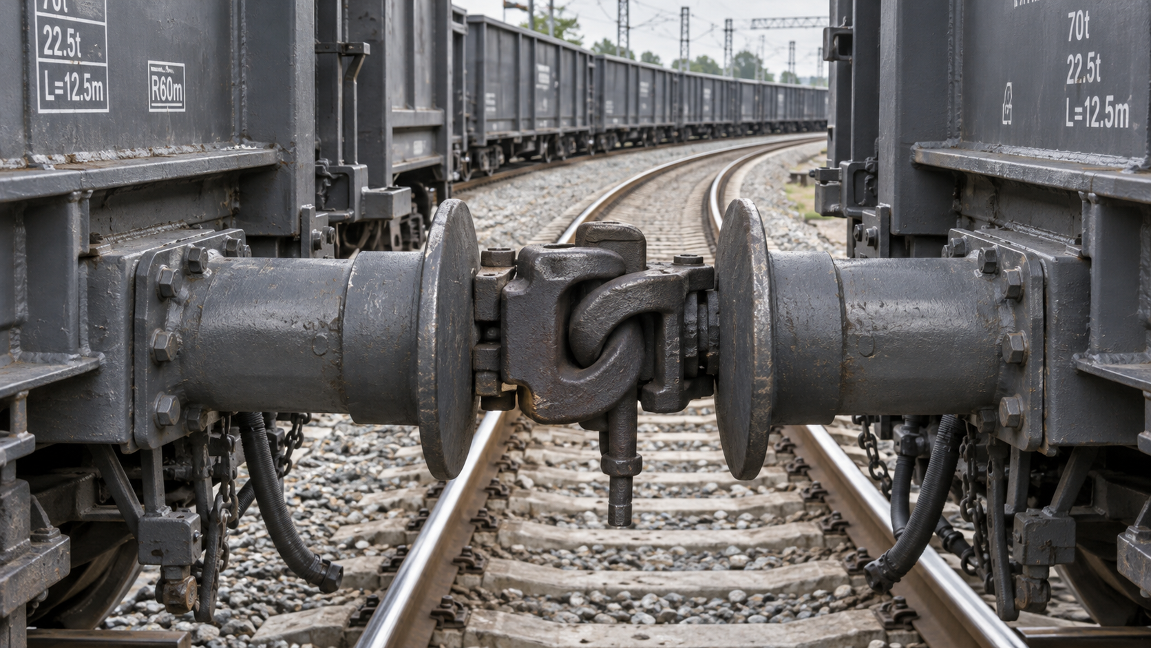
In a conventional side-buffer and screw-coupling arrangement, the components have different jobs. The draw hook, screw coupling, and associated draw gear transmit tensile forces when one vehicle pulls another. The two side buffers at each vehicle end transmit compressive forces when adjacent vehicles push together. Coupling adjustment influences how these components work as a system, but it does not make their functions interchangeable.
A buffer’s resilient element compresses under load, increasing the distance over which an impact is brought under control. Its damping characteristics determine how much energy is dissipated rather than returned as rebound. These are separate properties: a device can accommodate movement without adequately controlling the return of stored energy.
That distinction matters during shunting. A wagon contacting a stationary vehicle does not simply need a strong buffer housing. It needs a compatible force-displacement response, sufficient available stroke, and energy-handling capability appropriate to the operating conditions. Once a buffer exhausts its usable stroke, further compression can produce sharply increasing forces in the vehicle structure.
This explanation applies specifically to vehicles using side buffers. Many freight networks use centre couplers with draft gear that manages longitudinal loads through a different arrangement. Requirements for one system should not be transferred to the other without an engineering assessment.
Where buffer condition becomes an operational risk
Shunting impacts are the most visible loading event, but they are not the only one. Brake application, changes in gradient, traction changes, and slack movement can all create longitudinal compression within a train. Buffer condition therefore affects normal service as well as yard operations.
An ineffective buffer can transmit higher shocks into its mounting and the vehicle end structure. A seized mechanism may offer little useful movement; a damaged energy-absorbing element may respond differently from its intended characteristic. Either condition can be missed if an inspection checks only whether the buffer is still attached.
Unequal behaviour across the two sides of a vehicle end also deserves attention. If one buffer compresses or returns differently from the other, load sharing can become uneven. On curved track, where buffer contact is already asymmetric, that discrepancy can complicate vehicle interaction. It should be investigated rather than treated as an isolated cosmetic defect.
Buffers cannot compensate for excessive shunting speed, unsuitable train formation, or poor braking practice. Their capacity is finite. Treating a higher-capacity component as permission to relax operating limits confuses a protective device with an operating control.
Curves introduce a different hazard: loss of safe buffer contact
On a curve, adjacent vehicle ends rotate relative to each other and the buffer heads slide across their mating faces. Tight curves, reverse curves, vehicle overhang, and differences in buffer geometry can reduce the overlap between those faces. Under unfavourable conditions, buffer heads may pass beside one another and become interlocked, a condition commonly called buffer locking.
This is not merely a surface-wear problem. Buffer locking can impose harmful lateral forces and contribute to derailment risk. Assessment must consider the vehicle pair and track geometry together, including permitted coupling adjustment, buffer spacing, head dimensions, and relative vehicle-end movement.
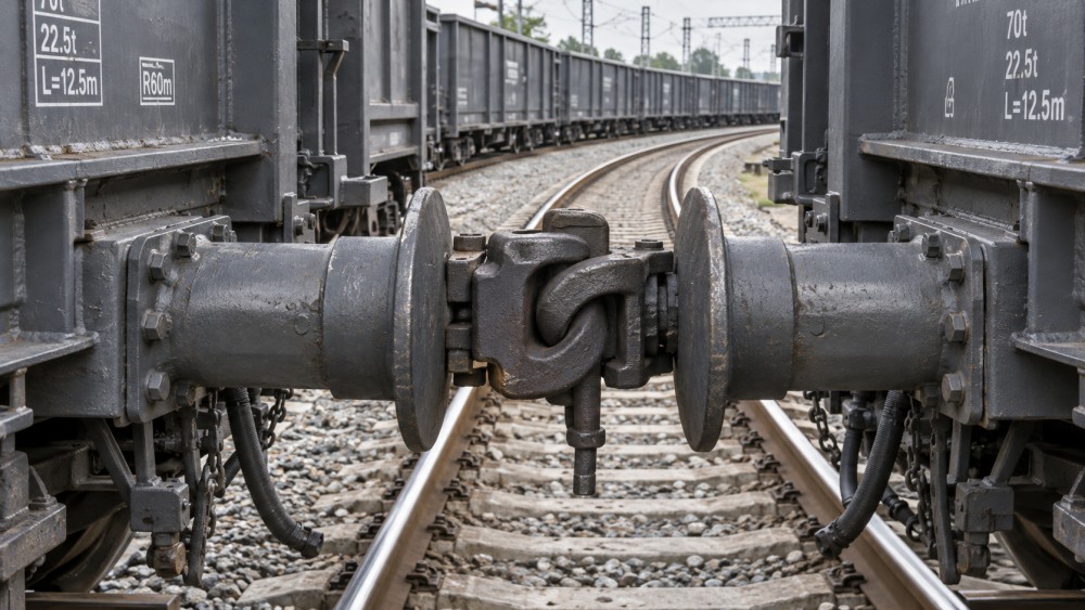
Buffer-head lubrication, where required by the approved maintenance instructions, helps manage sliding friction. It does not restore missing geometric overlap or make an incompatible vehicle combination acceptable.
Compatibility requires more than matching mounting dimensions
A replacement buffer may fit the existing mounting yet still be unsuitable. Installation dimensions establish only part of compatibility. Engineers also need to assess working stroke, force-displacement characteristics, energy absorption and dissipation, head geometry, installed projection, and the conditions under which performance has been verified.
A useful comparison separates the questions that drawings answer from those requiring performance evidence:
- Mechanical fit: Are the mounting interface, installed dimensions, and vehicle clearances correct?
- Compression response: How does force rise through the usable stroke, and what happens near its limit?
- Energy behaviour: What energy is absorbed and dissipated under the specified test conditions?
- Vehicle interaction: Are head shape, contact area, and curve compatibility suitable for the intended vehicle combinations?
- Service environment: Are temperature limits, contamination exposure, and maintenance requirements consistent with the duty?
Nominally similar buffers may use different internal technologies and exhibit different damping behaviour. Mixing types is not automatically unsafe, but acceptance needs documented compatibility, not an assumption based on appearance or a single capacity value. Pairing requirements at a vehicle end should follow the approved configuration.
For European applications, EN 15551 addresses railway buffers, while EN 15566 addresses draw gear and screw couplings. Applicable editions, vehicle requirements, and acceptance arrangements must be checked for the project. UIC requirements may also be relevant. A reference to AAR practice, by contrast, should not be treated as proof of compatibility with a European side-buffer arrangement; the underlying coupling systems and approval frameworks can differ.
Coupling adjustment is part of the safety assessment
Correct buffers can still perform poorly within an incorrectly adjusted connection. Excessive slack can allow greater relative movement before loads are taken up, increasing shock during transitions between tension and compression. Excessive tightening can create unwanted preload or constrain movement needed on curves, depending on the vehicle arrangement.
There is no universal screw-coupling setting that should be applied to every freight vehicle. Adjustment must follow the applicable operating instructions for the vehicles and route. Train formation, loading condition, and curve restrictions may influence those instructions.
The practical mistake is to inspect the screw coupling and buffers as unrelated items. A connection assessment should cover the draw hook, coupling links, screw mechanism, buffer heads, mounting condition, and the relationship between them. Evidence of repeated hard contact or unusual wear can point to an adjustment or compatibility issue rather than a defective buffer alone.
Personnel safety remains a separate requirement. Buffers create crushing zones, and their presence does not make manual coupling safe. Entry between vehicles, protection against movement, and handling procedures must follow the railway’s approved rules. No component inspection justifies approaching an unsecured vehicle pair.
Inspection should distinguish visible condition from proven performance
Routine checks are valuable because they identify defects before another loading event. Relevant observations include cracked or deformed heads, loose mountings, damaged housings, abnormal projection, leakage where applicable, and obvious differences between paired buffers. Wear patterns on the contact faces can also help identify abnormal interaction.
However, a clean exterior does not demonstrate internal performance. Depending on the design, deterioration may involve seals, springs, elastomeric elements, friction components, or fluid condition. Functional testing and overhaul intervals must follow the maintenance documentation; they cannot be replaced by a visual checklist.
After a significant impact, the assessment should extend beyond the buffer itself. Its mounting, supporting structure, draw gear, and adjacent equipment may have experienced loads outside normal service conditions. The absence of visible deformation is not sufficient evidence for unrestricted return to service where the applicable procedure calls for further examination.
Defect records become more useful when they connect component condition with operating circumstances. Recording vehicle identity, buffer type, impact history when known, inspection findings, and repair action helps distinguish recurring component faults from route-specific or operational problems. Replacement frequency alone cannot explain the cause.
Turning technical evidence into a fleet decision
For a fleet upgrade or replacement programme, start with the duty rather than the catalogue. Establish vehicle masses and formations, shunting practices, route geometry, environmental exposure, and the approved coupling configuration. Then compare candidate buffers against those requirements and identify any gaps in test evidence or vehicle-level acceptance.
Global Railway-Freight & Engineering (G-RFE) provides a technical intelligence context for this kind of assessment by connecting rolling-stock hardware with infrastructure, operating systems, and international standards. Its coverage across freight vehicles, track maintenance, signaling, intermodal terminals, and specialized machinery supports an important distinction: a component can meet its specification while the wider operating interface still needs attention.
Signaling and train-control systems, for example, manage movement authority and operational risk; they do not establish buffer compatibility or eliminate shunting impact loads. Equally, a well-specified buffer cannot resolve unsuitable terminal curves. These responsibilities need to meet in the engineering review, without being mistaken for substitutes.
Before approving a change, confirm the buffer specification, permitted pairings, maintenance limits, coupling instructions, and route restrictions in one reviewable record. If any of those are uncertain, resolve them before deployment. Coupling safety depends less on choosing the strongest-looking buffer than on ensuring that its behaviour remains compatible with the vehicles, track, and operating practices throughout service.
- Fleet Management Data Gaps: Why Rolling Stock Alerts FailTime : Nov 01, 2026
- Rolling Stock Performance Data: Which Fleet KPIs Matter Most?Time : Nov 01, 2026
- Reducing Freight Wagon Downtime with Condition Monitoring AlertsTime : Oct 31, 2026
Industry Briefing
Get the top 5 industry headlines delivered to your inbox every morning.