

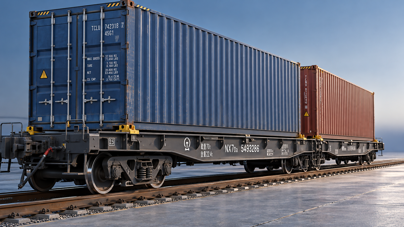
Intermodal Container Wagon Systems: How Axle Loads Limit Container Configurations
A container arrangement can fit a wagon’s deck yet exceed its permitted axle loads. Operational capacity depends on mass distribution, vehicle design, and route restrictions.
For technical evaluators assessing intermodal container wagon systems, the decisive question is whether each proposed loading pattern remains permissible throughout the intended operating corridor.
Container mass, longitudinal placement, wagon tare, and bogie geometry determine that answer. Approved loading diagrams translate these interacting constraints into configurations operators can actually use.
Why deck capacity does not establish usable payload
A wagon advertised for three twenty-foot containers offers a geometric arrangement. That description does not establish whether three heavily loaded units can travel together.
Technical assessment must separate container positions, maximum vehicle gross mass, permissible payload, and individual axle loads. Each describes a different boundary on operational capability.
For a conventional four-axle wagon, multiplying the applicable axle-load limit by four provides an initial gross-mass ceiling, subject to other vehicle and route restrictions.
Subtracting wagon tare gives a preliminary payload allowance. However, this calculation assumes sufficiently balanced loading and cannot establish whether a particular container arrangement is acceptable.
A lightly loaded wagon can overload one bogie when containers concentrate near one end. Unused capacity elsewhere does not compensate for that local exceedance.
The practical capacity of intermodal container wagon systems therefore depends on the cargo mix and route, rather than a single catalogue payload figure alone.
Which limit governs the proposed movement?
Begin with the wagon’s authorised loading conditions and the infrastructure restrictions applying to every route segment. The most restrictive applicable condition governs the movement.
Check permissible axle load alongside mass per unit length, bridge restrictions, speed conditions, and any vehicle-specific limitations. These controls address different infrastructure loading effects.
A route compatible with a stated axle load does not automatically accept every wagon length or load distribution. Vehicle geometry also affects bridge loading.
In European assessments, EN 15528 provides a framework for relating vehicle loading characteristics to infrastructure capability. Applicable editions and infrastructure-manager requirements still require verification.
For North American operations, assess the relevant AAR requirements together with railroad acceptance conditions. Gross rail load ratings alone do not establish universal route access.
Also distinguish infrastructure compatibility from container compliance. A container’s permitted gross mass does not establish acceptable wagon axle loading, even when its lifting arrangements comply.
Record restrictions for the complete journey, including port access lines and diversion routes. A short restricted section can determine the configuration available throughout service.
How container position changes bogie and axle loads
For an initial assessment, model a conventional wagon body as a beam supported at two bogie centres. Each container contributes a position-dependent support reaction.
The relevant position is the container’s actual longitudinal centre of gravity. Its geometric midpoint is only an approximation when the internal cargo distribution is unknown.
For bogie-centre spacing L, a container of mass m positioned distance x from the first bogie contributes the following mass-equivalent reactions under static equilibrium:
Second bogie: R2 = mx/L
Sum these contributions for every container, then add the wagon’s tare reactions at each bogie. Use measured or documented tare distribution where it is available.
Dividing each bogie reaction by two gives an initial axle-load estimate for a two-axle bogie, assuming equal load sharing within that bogie under assessment.
This simplified calculation does not establish individual wheel loads, suspension behaviour, or dynamic acceptance. Manufacturer-approved loading conditions remain necessary for an operational release decision.
Longitudinal balance is also separate from transverse balance. Cargo concentrated against one container side can create unequal wheel loading despite acceptable calculated bogie totals.
A worked example: acceptable total mass, overloaded rear axles
Consider an illustrative four-axle wagon with 22 tonnes tare, equally distributed between its bogies. Bogie centres are 14 metres apart; axle limits are 22.5 tonnes.
The initial gross-mass ceiling is therefore 90 tonnes, giving an arithmetic payload allowance of 68 tonnes before loading-pattern restrictions or other applicable limits intervene.
Now place 40 tonnes of combined container gross mass on the wagon. Its total gross mass reaches only 62 tonnes, comfortably below that preliminary ceiling.
If the combined cargo centre lies midway between bogies, each bogie supports 20 tonnes of container mass plus 11 tonnes tare, producing 15.5 tonnes per axle.
Shift that combined centre to 12.5 metres from the first bogie. The second bogie then receives approximately 35.71 tonnes from the containers alone under static equilibrium.
Adding its 11-tonne tare share raises the second bogie reaction to approximately 46.71 tonnes. Equal axle sharing gives 23.36 tonnes per axle, exceeding the limit.
The example isolates load distribution; it does not represent an approved container arrangement. Actual positions must match available supports, locking locations, and authorised loading diagrams.
Its engineering implication is direct: substantial unused gross-mass capacity can coexist with an overloaded axle group. Total payload alone is therefore an inadequate acceptance criterion.
Which container combinations need closer examination?
Mixed twenty-foot and forty-foot arrangements deserve particular attention because container positions and masses interact. Equal occupied length does not imply equal bogie loading across configurations.
Two twenty-foot containers can differ substantially in gross mass. Placing the heavier unit toward an outer position may exhaust one bogie’s capacity before reaching total payload.
A long container spanning central supports may distribute mass more favourably, but its actual cargo centre still matters. Length alone cannot establish a balanced load.
Empty containers require attention when paired with dense cargo. Their low mass can leave an apparently full wagon strongly biased toward the loaded container’s end.
Tank containers and other concentrated loads also require checks against approved support arrangements. Acceptable axle reactions do not prove that local frame loads are acceptable.
For articulated wagons, adjacent platforms can contribute to a shared bogie. Assess the complete coupled load path using the manufacturer’s model and loading documentation.
For double-stack equipment, axle limits interact with well capacity, stacking rules, vertical centre of gravity, and clearance. Passing one check cannot establish overall configuration acceptance.
What evidence should a technical evaluator request?
Request loading diagrams specific to the wagon variant, including permitted container sizes, locking positions, mass combinations, and restrictions for asymmetric loading or partially occupied decks.
Obtain tare mass and its distribution, bogie-centre dimensions, axle and bogie ratings, and structural load limits. Identify whether optional equipment changes these documented values.
Confirm that diagrams apply to the actual service conditions, including relevant speed and route categories. Similar-looking wagons can have different authorised loading conditions and restrictions.
For container inputs, use verified gross mass where available. Under SOLAS, VGM supports maritime loading control; it does not certify an acceptable rail loading configuration.
Where internal cargo distribution could affect acceptance, obtain centre-of-gravity information or apply the prescribed conservative assumptions. A gross-mass figure alone cannot locate the load.
Ask suppliers to explain how loading software handles shared bogies, tare imbalance, and missing data. Outputs should identify the governing restriction and underlying wagon configuration.
Evidence should connect design capability to an approved operating envelope. Brochure capacity figures and generic compliance statements cannot demonstrate acceptance of a particular loading pattern.
A practical sequence for accepting or revising a load plan
First, identify the exact wagon, intended route, operating conditions, and container inventory. Establish applicable limits before optimising positions or comparing theoretical payload opportunities across alternatives.
Second, map each container to an approved position and support arrangement. Reject incompatible geometry immediately, before spending time calculating a configuration that cannot be secured.
Third, calculate gross mass, bogie reactions, and estimated axle loads using documented inputs. For articulated vehicles, include contributions from every platform affecting a shared bogie.
Fourth, check structural, wheel-load, clearance, and route requirements using the applicable procedures. Static axle calculations form one part of this assessment rather than complete approval.
Where a configuration fails, evaluate permitted repositioning, a different container pairing, reduced container mass, or another wagon type. Recalculate every affected constraint after each revision.
Finally, retain the accepted loading diagram, mass inputs, assumptions, and route conditions with the load plan. Changes to any governing input should trigger reassessment before dispatch.
Compare wagon systems using usable capacity on your traffic
Procurement comparisons should test representative container mixes against actual corridors. Include heavy twenty-foot units, mixed masses, partial loads, and any articulated configurations relevant to operations.
Measure accepted payload, rejected loading combinations, repositioning needs, and wagons required per shipment. These results connect engineering restrictions with terminal workload and transport cost directly.
A lighter tare improves arithmetic payload, but its commercial benefit depends on the governing constraint. Loading geometry or route restrictions may prevent using the additional allowance.
Evaluate operational flexibility alongside maximum capacity. A system accepting more common container combinations can reduce planning exceptions, even when its nominal payload appears similar overall.
Conclusion: approve configurations, not capacity claims
Axle-load limits constrain both container mass and placement. A usable configuration must satisfy individual load limits, approved support arrangements, structural requirements, and the intended route.
For technical evaluators, the strongest decision combines documented wagon capability with configuration-specific calculations. This establishes how much traffic a wagon can carry under real operating conditions.