
Intermodal Rail Engineering Design: Matching Track Layout to Terminal Throughput

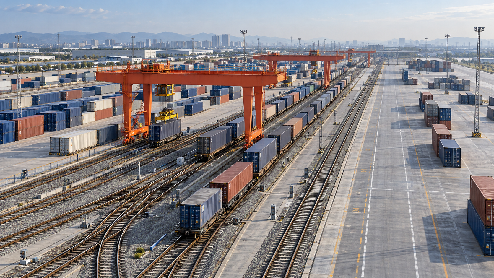
A terminal can have enough track to hold its planned trains and still miss its throughput target. An arriving service may block the switching lead, a departure may wait for inspection space, or a crane may sit idle because the next wagon group cannot reach the loading track. Track capacity becomes useful only when trains, handling equipment, and road vehicles can move through the terminal in the required sequence.
Effective intermodal rail engineering design starts with that sequence. The layout must accommodate train length, arrival patterns, handling demand, and departure windows while preserving space for disruption and maintenance. The strongest option is the one that delivers the required service reliably at an acceptable whole-life cost.
Translate throughput targets into an operating plan
An annual container forecast is insufficient for sizing a rail terminal. The same annual volume can produce very different infrastructure requirements depending on whether traffic arrives evenly or concentrates around vessel calls, overnight rail services, or customer dispatch windows.
Define throughput units before comparing layouts. TEU measures container capacity, while physical containers determine many handling tasks. A crane lift, a wagon movement, and a truck transaction represent different workloads. A forecast expressed only in TEU can conceal the handling demand created by the container mix and operating method.
The design basis should describe:
- Train characteristics: operating length, wagon configuration, loading profile, locomotive arrangements, and expected future changes.
- Service pattern: arrival and departure windows, directional balance, and the likelihood of overlapping services.
- Handling demand: containers exchanged per visit, unloading and loading sequences, and additional moves through storage.
- Occupancy: time spent receiving, inspecting, positioning, handling, assembling, and releasing each train.
- Performance requirements: acceptable turnaround, connection reliability, and recovery from delayed arrivals or equipment outages.
These inputs should form a workable operating timetable. If the timetable requires two movements to use the same route simultaneously, adding loading-track length elsewhere will not resolve the conflict.
Size tracks by usable length and occupancy
Track length on a drawing is not automatically usable train length. Clearance points, signals, stopping allowances, turnout positions, buffer stops, and locomotive positioning can reduce the length available for standing vehicles. A train that fits geometrically may still prevent an adjacent route from being used.
Establish a consistent definition of usable length across the project. Arrival and departure tracks must accommodate the intended standing formation, including locomotives where required. Loading tracks need enough accessible length for the wagon groups being handled, with allowance for equipment limits and operational clearances.
Full-train loading tracks can reduce splitting and reassembly, but they require suitable land and equipment coverage. Shorter tracks may suit constrained sites or smaller traffic volumes. Their cost comparison must include the switching moves, staff time, route occupation, and handling interruptions associated with dividing trains.
Use track-hours as an initial screening tool
A useful early calculation is:
Required track-hours = the sum of each train’s occupancy time within the track group being assessed.
Compare this demand with the available track-hours during the operating period, allowing for maintenance and other restrictions. Calculate arrival tracks, loading tracks, and departure tracks separately where their functions differ. Combining them can hide a shortage in one part of the terminal.
This calculation identifies basic capacity pressure, but it does not establish timetable feasibility. Several trains may need the same track group during a short arrival window even when average daily occupancy appears low. Average utilization must be checked against simultaneous demand and route conflicts.
Give arrivals, switching, and departures room to function
Arrival and departure tracks provide a buffer between the external railway and terminal handling operations. Without sufficient receiving capacity, a late-running train can occupy the route needed by another service. Without departure capacity, a completed train can remain on a loading track and delay the next handling cycle.
Separate track functions are useful when inspections, locomotive changes, or dispatch preparation take place outside the loading area. However, dedicated tracks also consume land and may stand unused during quieter periods. Shared tracks can work where the timetable supports them and switching arrangements allow their roles to change without trapping trains.
The terminal throat—the area where tracks converge through turnouts—often determines whether this flexibility is practical. A large group of sidings can still depend on one shared route. Every arrival, departure, and internal transfer then competes for access through that point.
A dedicated switching lead has limited value if it is too short for the planned wagon group. Likewise, double-ended tracks provide limited operational benefit if both ends feed a route that remains occupied throughout a critical period.
Trace each proposed train movement through the layout, including locomotive release and repositioning. Identify where trains reverse, which routes they occupy, and whether another train can continue working during the movement. This exposes conflicts that a simple track-count comparison misses.
Design the loading area around the handling system
Track geometry and handling equipment should be selected together. Rail-mounted gantry cranes, rubber-tired gantry cranes, and reach stackers create different requirements for track spacing, pavement, storage, vehicle circulation, and equipment access.
A gantry arrangement may serve several parallel tracks and adjacent transfer lanes, but its benefit depends on working coverage and interference between cranes. Reach stackers offer flexibility in suitable operating conditions, while requiring maneuvering space, pavement capacity, and controlled interaction with vehicles and pedestrians.
Nominal equipment productivity does not directly translate into terminal throughput. Actual handling time also includes travel, alignment, container identification, access to the required wagon position, and waiting for the transfer vehicle. Rehandling occurs when containers must be moved again before reaching their next transport leg.
For layout evaluation, distinguish productive lifts from total moves. A configuration that reduces travel distance can still increase workload if storage positions create extra rehandling. Similarly, adding a crane may produce little benefit if cranes interfere with one another or trucks cannot reach the transfer area consistently.
Examine the interface beyond the tracks. Gate processing, internal roads, chassis availability where relevant, and container storage can restrict rail performance. A train may be ready to unload while the receiving stack lacks suitable space; a departure may be delayed because outbound containers have not reached the loading area.
Electrification also needs an explicit operating concept. Overhead electrical equipment can constrain lifting operations, so the design must resolve locomotive access, electrical clearances, isolation arrangements where applicable, and transfers into the handling zone. These decisions influence both layout and cycle time.
Test disrupted operations before choosing a layout
A layout should be assessed against a representative operating day and credible disruptions. A timetable that works only when every train arrives on time offers little protection against normal variability.
Useful scenarios include closely spaced late arrivals, an extended inspection, temporary loss of a handling machine, a blocked loading track, and an unusually heavy exchange on one service. The purpose is to see how the terminal recovers and whether delays spread to other trains or the external network.
Early options can be screened with movement diagrams and time-based track occupation charts. More complex terminals may justify discrete-event simulation, in which trains, cranes, trucks, and storage positions compete for resources over time. The model should represent route locking and release, switching sequences, handling variability, and operating restrictions that materially affect capacity.
Evaluate more than total daily throughput. Compare train turnaround, departure punctuality, waiting time at the terminal boundary, throat occupancy, handling-equipment queues, and recovery time after disruption. A design can process the daily volume while repeatedly missing departure windows.
Model assumptions deserve the same attention as the results. Constant crane productivity, immediate route availability, or unlimited storage can make an impractical layout appear efficient. Use assumptions consistent with the proposed equipment, staffing, maintenance access, and working rules.
Protect expansion without weakening the first phase
Future capacity requires more than an empty strip beside the railway. Additional tracks may need longer crane coverage, a different throat arrangement, drainage alterations, stronger pavement, or more storage and road access. Utility corridors and permanent buildings can make an apparently straightforward extension difficult.
Reserve space for the expansion mechanism the operating plan is likely to need. Longer trains may require extended reception tracks and revised turnout positions. More services may require another receiving track or independent access route. Higher exchange volumes may place greater pressure on handling equipment and storage than on track length.
Construction staging also affects the value of an expansion plan. Connecting a future turnout or extending crane infrastructure may interrupt existing operations. The concept design should identify these interfaces and the temporary operating arrangements required to build them.
Track formation, drainage, pavement, and maintenance access belong in this assessment. Settlement or water-related restrictions in the loading zone can disrupt both wagon positioning and equipment operation. Adequate access for inspection and repair helps preserve the capacity the terminal was designed to deliver.
Make the investment decision traceable
Compare options against the same demand profile, operating assumptions, and service requirements. Include land, trackwork, handling equipment, signaling, pavement, drainage, and construction staging in capital cost. Operating comparisons should account for switching effort, staffing, equipment travel, maintenance, and the consequences of unreliable departures.
Applicable infrastructure, rolling-stock, electrical, and operational requirements must be translated into design criteria. A general reference to UIC, EN, or AAR does not establish suitability: the relevant requirements depend on the railway system, equipment, and infrastructure manager. Clearances, axle loads, braking arrangements, and signaling interfaces need coordinated treatment.
Before approving the preferred layout, require three connected deliverables: a drawing showing usable track lengths and movement routes; an operating plan explaining how trains are received, handled, and dispatched; and capacity evidence showing performance under peak demand and defined disruptions.
Each physical feature should have a clear operating purpose. If an additional siding is proposed, identify which conflict it removes. If shorter loading tracks reduce construction cost, quantify the resulting switching workload. Approve the arrangement when the geometry, operating plan, and capacity assessment support the same throughput commitment.
- Rail Port Systems: Comparing Automation Costs and Long-Term SavingsTime : Oct 30, 2026
- Rail Port Terminal Costs: Budgeting for Track, Cranes and SoftwareTime : Oct 30, 2026
- Rail Port Systems Cost: What Drives Installation and Operating Expenses?Time : Oct 30, 2026
Industry Briefing
Get the top 5 industry headlines delivered to your inbox every morning.